Thermal Consideration in LED Lighting
Why is thermal management is needed in an LED lighting system?
LEDs are more efficient than incandescent sources and have different thermal challenges. Unlike incandescent tungsten-filament light bulbs, high-power LEDs do not radiate heat. Instead, LEDs conduct heat from their PN junction to the thermal slug on the LED package. In an LED, the heat path includes thermal impedances among different components like the slug, board, and heatsink.
The primary cause of LED failure is improper thermal management. This is exceeding the maximum junction temperature specification, typically 150 °C. This impacts the performance of LED parameters, like color and brightness are sensitive to temperature. Therefore, designers need a basic understanding of thermal design and performance.

Fundamental modes of heat transfer & cooling technique
There are three basic modes of heat transfer; conduction, convection and radiation. The process of heat transfer in solids is known as conduction. In liquids and gases, it is known as convection and radiation, respectively.
Conduction, along with radiation, is responsible for cooling in LEDs. Passive cooling is achieved by attaching different heatsinks directly to the LED mount. The heat is conducted from the junction of the LEDs to the heatsink and from there it is radiated to the surrounding environment.
In case of active cooling, a fan is used along with the heatsink to further minimize the temperature and maximize efficiency. A benefit of active cooling is that the physical size of the heatsink required is two-thirds smaller and lighter. This reduces the heatsink cost. Heatsinks, heat spreaders, heat pipes or thermal interface materials (TIM) are also used to maintain operating temperatures within range.
Effect of heat on the LED parameter
Electrical, thermal and optical parameters influence output characteristics of LEDs. The following figure explains how light output is related to electrical and thermal parameters.
Theoretically, a higher drive current increases the light output. However, it increases the dissipated power and ultimately hurts the light output and efficiency. Then again, a higher junction temperature causes a reduction in the forward voltage of the LED, making the dissipated power even higher for a constant current source. Similarly, the dominant wavelength, light output and forward voltage of an LED are interdependent as listed.

Light output decreases as temperature increases
The attached figure shows the relationship between junction temperature and luminous flux. It is apparent that AlInGaP LEDs are the most sensitive to heat. It can be observed that for luminous flux >80% of a white LED, the junction temperature must be maintained below 100°C. In the case of amber, the output flux decreases sharply with the increase in junction temperature.

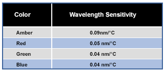
Dominant wavelength (shifts color) with temperature
TJ increases the wavelength or color will shift. The dominant wavelengths of LEDs are dependent upon the junction temperature. Typical values for one-watt high brightness by color can be read in the attached table. It is apparent that amber is the most sensitive as it will shift 0.09nm/°C. Assuming an ambient temperature range of 10 to 40° Celsius for indoor lighting, the shift in dominant wavelength for amber is 2.7nm (40 - 10 * 0.09) over a 30° temperature range.
Forward voltage decreases with temperature
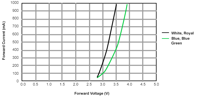
When the temperature rises, VF decreases by 2mV/°C. This is important. Assuming that when the LEDs are connected in series, VF change should not be a serious problem, since it’s driving constant current. However, if LEDs are connected in parallel, VF will drop as the temperature rises, causing an increase in current. As the current rises TJ will continue to increase, resulting in a further drop in VF until equilibrium is reached. In contrast, as low temperatures VF increases, causing the current to drop, this may make it difficult to obtain the required luminosity during constant voltage operation.
Lifetime decreases with temperature
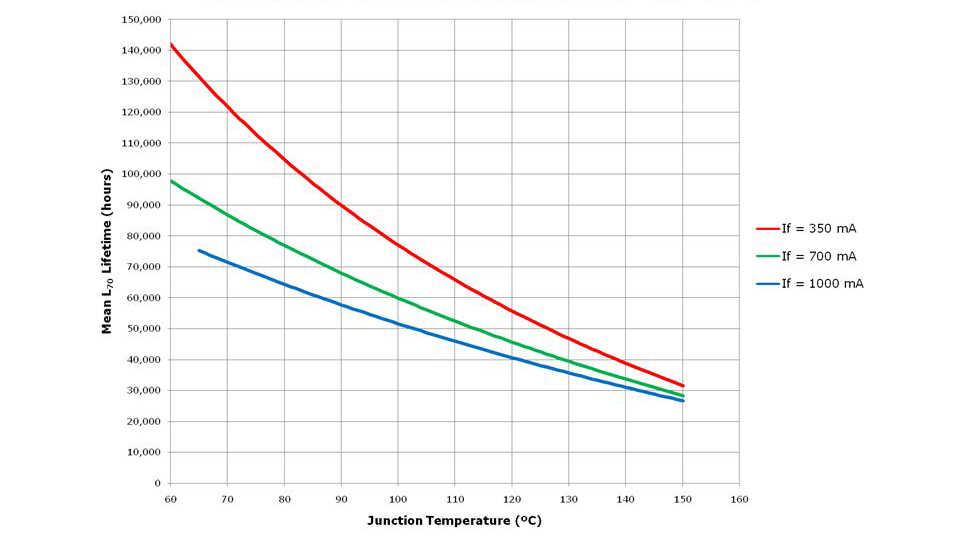
The reliability of an LED is a direct function of junction temperature. A higher junction temperature tends to reduce lifetime LED lifetimes. IES LM-80-08 is a standard that specifies how LED manufacturers and lighting manufacturers may test LED components to determine their performance over time. An LM-80-08 report is used to predict LED lumen maintenance under various temperatures and drive current operating environments. This graph explains the relation between L70 lifetime and junction temperature. It is observed that the LED lifetime decreases with the increase in junction temperature. The L70 lifetime of an LED defines the time taken for the LED output lumens to reduce from 100% to 70%.
Optimal heat distribution for higher efficiency using PCB material and Heatsink
The preceding discussion explained why, the heat generated from the LED must be moved away from the junction area. It follows that the PCB material used plays a pivotal role in the conduction of heat away from the LED in the absence of a proper heatsink. Using a heatsink instead of depending solely on the LED mount or the PCB used makes the device compact. The net surface area is consequently increased for better heat radiation. This section will discuss different PCB materials and also heatsinks and their applications.
PCB
Different kinds of PCB materials are targeted towards specific applications. A few of the popularly used PCB materials includes FR4, Ceramic, MCPCB among others. FR4 PCB materials are avoided in deployments as they are poor conductors of heat. Ceramic PCBs, like aluminum nitride (AlN) and aluminum oxide (Al203), are extremely thermally conductive, in contrast to FR4. In applications where heat is a real issue, like LED lighting, it is a good idea to move away from standard FR4 boards towards ceramic boards or other metal core PCBs. This is as metal core boards can more easily carry excess heat away from hotspots which may ultimately damage the board by reducing the life of semiconductor junctions.
Other metal core PCB materials, including aluminum and beryllium, can include copper and steel alloy. Steel alloys provide stiffness that cannot be had with copper and aluminum but are not as effective at heat transfer. Copper is the most efficient material to transfer and dissipate heat as part of the printed circuit boards, but it is comparatively expensive.
Heatsink
A heatsink is a passive device used to exchange heat from electronic or any mechanical devices to air or any liquid coolant, thus helping in regulating the device temperature. The idea of the heatsink is to increase the total surface area so that the heat can be radiated efficiently. Heatsinks are generally used in stand-alone mode or with a fan to achieve better cooling, and the same goes with a heatsink with LEDs.
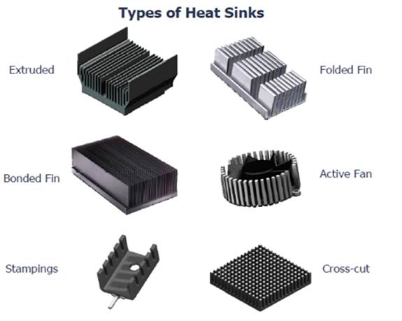
There are three common types of heatsinks: flat plates, die-cast finned heatsinks and extruded finned heatsinks. The common material used for heatsink construction is aluminum, although copper may be used with an advantage for flat-sheet heatsinks.
Heatsink thermal radiation is a function of surface finish, especially when the heatsink is at higher temperatures. A painted surface will have a greater emissivity compared to a bright, unpainted one. The effect is noticeable with flat- plate heatsinks, where about one-third of the heat is dissipated by radiation. The color of the paint used is relatively unimportant. The thermal resistance of a flat-plate heatsink painted gloss white will only be about 3% higher than that of the same heatsink painted matte black. With finned heatsinks, painting is less useful since heat radiated from most fins will fall on adjacent fins, but it is still worthwhile. Both anodizing and etching will decrease the thermal resistance.
Heatsinks can be classified in terms of manufacturing methods and their final form shapes. The most common types of air-cooled heatsinks include:
- Stampings
- Extrusion: natural/ forced convention
- Bonded/Fabricated Fins
- Castings:
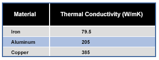
Thermal Conductivity of Common Heatsink Materials. Copper is better for thermal, but the cost is higher compared to Aluminum.
TIM (Thermal Interface Material)
In a typical system, the LED is soldered to a PCB, either metal core (MCPCB) or FR4, which is then usually attached to a heatsink. When selecting a heatsink, the portion of the heatsink that is in contact with the LED or MCPCB must be perfectly flat. A flat contact area allows the use of a thinner layer of thermal compound, which will reduce the thermal resistance between the heatsink and LED source.
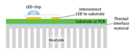
The TIMs are critical to minimizing the air gaps between the heatsink and the PCB. They not only provide a thermal interface between the PCB and the heatsink, but, depending on the application, these can have other functions as well, like electrical insulation, or making a mechanical connection. Many types of TIMs are used in LED systems including greases, tapes, pads and epoxies. Each has its advantages and disadvantages, depending on the application. The following table shows a few of the benefits and drawbacks of various materials.
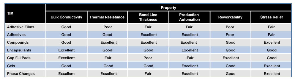
Multiple characteristics must be considered when selecting a TIM, and must not be limited to only thermal conductivity. The bond line thickness of the material is frequently overlooked. Sometimes, a thinner TIM with poor thermal conductivity has a lower thermal resistance compared to a thicker TIM with better thermal conductivity. Both these attributes must be considered during TIM selection.
Calculating Heatsink Requirement – Thermal Design
For any standard heatsink, size and thermal resistance are two primary factors to be considered in the overall design goal. Thermal resistance is a measure of the ability of the package to conduct heat from the chip to the environment. The lower the Rth, the larger the heatsink should be, meaning it will dissipate more heat.
Given an existing thermal resistance of 8°C/W between the junction and the solder point, it is crucial for the end product to be designed in a manner that minimizes the thermal resistance from the solder point to ambient to optimize the life of the LED.
The thermal resistance of an LED package is defined as the ratio of:
Temperature differences between the junction of the LED and the ambient atmosphere over the power dissipation due to a current flowing through an LED accompanied by a forward voltage drop across the device.
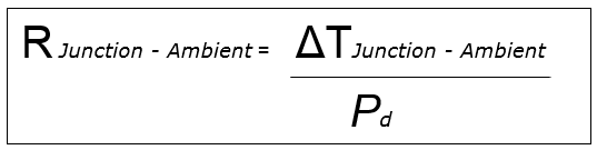
Where
ΔT = T Junction – T Ambient
Pd = Forward current (If) * Forward voltage (Vf)
Junction temperature -The temperature of the LED junction (Tj) is the sum of the ambient temperature (Ta) and the product of the thermal resistance from junction to ambient and the power dissipated.
Tj = Ta + (Rth j-a x Pd)
As heat is generated at the junction of the LED die, its thermal path can be summarized and modeled as shown in the figure below.
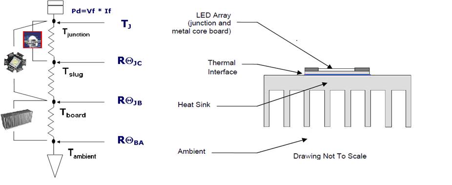
RΘJ -A = RΘJ - S + RΘS - B + RΘB - A
RΘJ -B = RΘJ - S + RΘS - B
Where
RΘJunction-Slug (J-S) can be found in the specific datasheet, Slug and solder point are the same.
RΘSlug-Board(S-B) includes the thermal resistance from the slug in the die, some supplier mentioned Junction to Case & junction to solder-point.
RΘ board-ambient (B-A) is the thermal resistance from the heatsink to ambient.
The following is an example to determine the heatsink required for an MCPCB LED at a maximum ambient temperature of 60°C.
1. Determine system thermal resistance RΘJ-A:
RΘJ –A
- = ⊗T J -A / Pd
- = (90°C -60°C) / 1.3W
- = 23°C /W
TJ = 90 °C (Tj to achieve 70% lumen maintenance at 50K hours)
TA = 60 °C
Pd = Vf * If = 3.51V*0.350A = 1.3W (Assume highest Vf and If)
2. Determine heatsink thermal resistance RΘ J-B:
The thermal resistance between the LED slug and board (heatsink), depends on the surface finish, flatness, applied mounting pressure, contact area, and the type of interface material and its thickness. With proper design, it can be minimized to less than 1°C/W (this will be on the high end based on the mounting method)
The thermal resistance from junction to slug is listed in the datasheet as 8°C/W.
RΘJ-B = RΘJ-S+ RΘS-B
= 8°C +1 °C /W
= 9 °C /W
3. Determine heatsink thermal resistance RΘ B -A :
RΘ J -A = RΘ J -B + RΘ B -A
RΘ B –A = RΘ J -A - RΘ J -B
= 23 °C/W - 9 °C/W
= 14°C/W
4. Select 14°C/W Heatsink
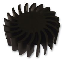
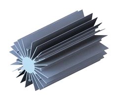
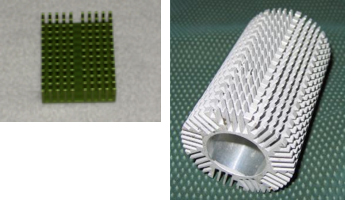
Rth must be equal or lower than the calculated value, the lower the value, the higher the thermal performance. The images below show a comparison of sizes between two heatsinks with different Rth value.
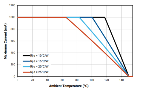
D-rating curve:
D-rating curve is very important in an LED system. The total system-level thermal resistance is RΘJ –A, this quantifies how well each component transfers thermal power.
Given an Rth j-a (thermal resistance from the die to ambient) at a particular ambient temperature, you may need to back off the current so that you don’t exceed the maximum Tj.
The graph shown the maximum drive current versus ambient temperature for a few system thermal resistances.
To use the current de-rating curve, the system-level thermal resistance must be calculated (typically defined as “junction to ambient,” or ΘJ-A), the ambient temperature must also be known, and from this, the maximum drive current for this thermal design can be determined from this d-rating graph.
Featured Product